A stepper motor is a motor that moves in steps. Well, DUH! Isn’t that obvious? But it may not be. Because the notion of moving in steps is not as trivial as we may think. In fact, the ability to move in steps is so desirable an entire fleet of motors had to be devised in order to achieve this concept. Have in mind a brushed DC motor or an AC induction motor can not move in steps. If you were to close the loop and add all sorts of algorithms, you may be able to emulate said motion, but this will not be easy… So how does a stepper motor does it?
In order to understand why a stepper motor can move in steps it is best to understand why a Brushed DC motor can not move like that. A DC motor is an automatic commutation machine. That is, when a voltage is applied and a current flows through the rotor electromagnet, as the rotor moves, the inductor which was energized will move away only for a new inductor to take its place. Since the commutator is built such that these connections are made ad infinitum, the motor rotates… well… ad infinitum! Stepping is then, not intrinsically possible.
But if we remove the commutator and we find a way for the electromagnet commutation to be made external to the rotation, we can then control this rotation. In other words, I can apply a magnetic field in such a way that my rotor will move to a particular place, only to later move into the next position as I reapply a different magnetic field. And this is what a stepper motor is. It is a brushless dc motor (there are no brushes) in which we are given full control of the commutation. Because we decide which electromagnet is energized and when it is energized, we can control the position the rotor will assume and when this happens. We can call each one of these controlled motions, a step.
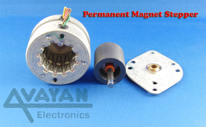
There are many ways to achieve what I just explained above. Per example, there are variable reluctance steppers, permanent magnet steppers and a combination of both techniques called hybrid steppers. Each technology has its advantages when it comes to sizing and cost. Permanent magnet and variable reluctance stepper motors will reside on the cheap side. Notice they are built using very low cost materials and mechanically speaking they are not necessarily very robust. For example, the rotor is mounted in brass bushings instead of ball bearings.
The Hybrid stepper motor is actually a better built machine, and as such, will be more expensive. Notice the ball bearings on the rotor. This allows for less mechanical losses due to friction, but at the same time, longer life. And why would you not enhance the life on a motor which has been so expensive? The construction of hybrid stepper motors is not trivial and their price tags will quickly signal this. The rotor now has many teeth to enhance higher stepping resolution the permanent magnet counterpart can not achieve. A laminate body will help with the release of thermal energy allowing for higher currents and larger torque capabilities.
Now, the three stepper motor styles I mentioned have to do with the construction. If we are dealing with how the magnetic fields are generated, then we are talking about how are we driving the motor. In this case, there are two major styles: Unipolar and Bipolar:
Unipolar Stepper Motor:
In unipolar stepper drive, the stepper is made out of four coils connected in a star configuration with a center tap. The center tap is connected to the positive power supply terminal and each one of the four windings is connected by means of a switch to the GROUND terminal. In the most tipical full step mode, each switch is enabled independently from the others, so current flows from VM to GND. Since current only flows in one direction, a single electromagnet polarity is generated. Hence, the name Uni-Polar.
The actuation of a Unipolar Stepper Motor is quite simple. The idea is that by polarizing each subsequent electromagnet, the rotor is moved one step further. Hence the sequence is very important. Reversing the correct sequence will result in the motor rotating in the opposite direction.
Bipolar Stepper Motor:
The Bipolar stepper motor is in fact a two electromagnet motor, also known as phases. You may see the typical nomenclature for these phases as PHASE A and PHASE B.
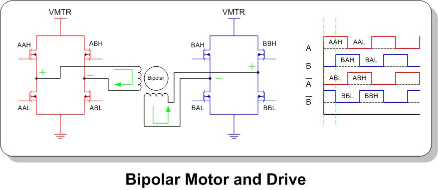
Each one of these phases is connected to an H Bridge driver. The idea is that by correctly polarizing the electromagnet different combinations of pulls and pushes can be obtained. Since an H Bridge is utilized, current can flow in both directions. Hence, the electromagnetic field generated is in essence of dual polarity. Hence the name BI Polar.
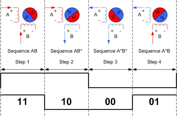
The actuation of the Bipolar Motor is a little bit more complex than the unipolar. In this case we must control current flow in both directions so that the push and pull subsequently generates the next step. Luckily, the sequence is fairly simple and 100% standard, as shown below:

What we have here is a square wave being applied on one of the two windings and the very same square wave, but with 90 degrees out of phase, applied to the second winding. Which square wave leads the other will determine the motor rotation direction. In other words, if PHASE A leads PHASE B the motor moves clockwise but if PHASE A lags PHASE B, then the motor moves counterclockwise. On the previous statements the CW and CCW directions were assumed arbitrarily, so in reality either direction is possible. What we must understand is the nature of the opposing directions as one PHASE leads or lags the other.
Notice that as the current enters the winding a magnetic polarity is generated which is opposite to the magnetic polarity if the current was exiting the winding. Since there are two electromagnets, and only two possible combinations (current goes in or goes out), there are a maximum of four possible states. I have called these four states 11-10-00-01. It is very important to note that only one phase changes at a time. For example, you don’t see changes such as 11-00 or 10-01. This would cause a jump in our sequence and the motor would not react in a pleasing manner.
Repeating this sequence continuously would allow the motor to move continuously on one direction. If we change the order of the sequence (we do 01-00-10-11 and so on) the motor will move in the opposite direction. Hence direction control is easily achieved by controlling the sequence order. This is precisely the same as what I mentioned earlier when I talked about one phase leading or lagging the other. By reversing the sequence what you are actually doing is making whatever phase was lagging, now to be leading. This makes the bit banging of your microcontroller darn easy! Just get a look up table with the four values and cycle across them in one direction or the other.
Notice also that both electromagnets are energized at all times. On the sequences 11-10-00-01, the state represented by the “0” is not for zero current but for inversed polarity, so do not confuse this important aspect of polarization as the implications would be completely different. For example, this is one of the greatest differences from unipolar drive and bipolar drive. On Unipolar stepper motors, only one winding is energized, hence the torque is not as large as on the bipolar counterpart where both electromagnets are exerting forces at all times.
There is one last implication which may be obvious by now, but just in case I want to point out. As the bipolar stepper motor electromagnets become energized with one polarity or the other, they are atracting the rotor into the commanded position. However, at the same time, the very same electromagnetic force is repelling the rotor into the commanded position. That is, both attraction and repel forces, from different and similar magnets respectively, are being harvested.
The Stepping Action
Because we control both H Bridges, that is the magnitude of the current flowing, the direction of this current and the rate of current magnetic/direction change, there are a few abilities we gain. These are in no respective order:
Position Control: When we energize both electromagnets, the rotor will move to the commanded position. If we take our rotor to a known starting position, we can then obtain any given position by counting how many steps have been issued.
Speed Control: If we control the rate at which these steps are being generated, we are in essence controlling the rotor speed. For example, if we command 200 steps per second on a stepper that is 200 steps per revolution, we will obtain an angular speed equal to 1 revolution per second or 60 revolutions per minute. By changing the time from one step command to the next, we can obtain any speed the motor will react to.
Position Hold: If we energize the stator’s electromagnet but do not issue more steps, the rotor will stay in the position it has been commanded to reach. As long as the load the stepper motor is driving is not larger than a parameter known as the holding torque, the rotor will maintain its position. Try doing this with a DC motor!


4 comments for “What is a Stepper Motor?”