If you are driving inductive loads, whereas it is a brushed or brushless DC motor, stepper motor, solenoid or a relay, you must have experienced a little bit of a problem in the form of an unwanted current flowing in the unwanted direction. If you did not take this fact of the laws of physics into account, chances are you have had the only once enjoyable experiencing of smoking your transistor. Whether it was a bipolar transistor or a FET, if a mechanism to overcome this generated current was not put in place, said transistor will not last long. But why does this happen?
Lets take a quick look at what is happening with our inductor.
It is a known law of physics that inductors will not tolerate abrupt changes in current either when they are being charged or when they discharge. This is in essence because as you apply a voltage and a current starts to flow through the conducting element, a magnetic field is generated. The magnetic field at the same time generates a current that fights the incoming current, making the incoming current needing to fight its way into the inductor. Either way, and at the end of this charging ordeal, we can see that the energy that went into the inductor will be maintained in the form of a magnetic field. OK, enough with the basics.
Case A of our picture shows a current happily flowing into our inductor. I say happily because in essence nothing stops this flow. As soon as the FET is energized, the current starts to flow until the inductor saturates. But what happens when the FET is disabled? This will eventually happen, right? This may be fine except that all the energy stored inside the inductor will now want to get out of its cage, plus the current can not change abruptly so whatever was going in, must continue going out. As a result the inductor is now the source and the FET the load. But the FET is off!!! This angry current, as portrayed on case B, will not care too much about its path not being present. A path will be made, one way or the other! And as it is often the case, the voltage goes up in such a way that the FET is damaged.
We need to provide a way for this current to find a safe path which not encompasses the destruction of our transistor switch. And the solution often comes in the form of what is called a free wheeling diode. Notice the diode is placed such that while the FET is on, it can not conduct (its voltage from anode to cathode is negative). It is only when the FET is OFF, that the inductor operating as a source makes the voltage across the diode positive, hence making it conduct. In this case, the FET sees no current flow and no negative voltage.
But why do we need to bother about this when dealing with H Bridges? The previous example shows a simple single FET driver. Are H Bridges subjected to the same problems? Yes and No! In essence the problem still exist because inductive loads will still try to conduct through a disabled FET when said switch gets disabled. So an H Bridge would suffer the same fate as the single transistor driver if an alternate path is not provided. However, the H Bridge has enough alternate paths, and this is where current recirculation or decay modes come into play. Lets take a look at the H Bridge quickly.

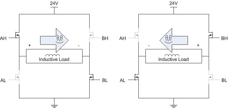
On an H Bridge you only enable as much as two FETs at any given time. It is completely forbidden to enable the two FETs on the same side, as this would lead to Shoot Through (a short circuit from power supply to ground). If you enable the hi side FET on the left side (AH), and the low side FET on the right side (BL), then the current flows from left to right. If the inductive load was say a DC motor, then the motor would spin in one direction, say clockwise. If on the other hand, you enable the high side FET on the right side (BH), and the low side FET on the left side (AL), then the current would flow from right to left. This has the desirable effect of turning the motor in the opposite direction, in this case counterclockwise.
Unfortunatelly, all is good only if we never disable those FET’s. Because as soon as you do, then the current will try to keep on flowing on the same direction, which should result in flames right? Not necessarily… What if we add freewheeling diodes to save the day? Four of them should do, right? As it turns out, we do not need them! Like I said before, there is already more than plenty alternate routes and all we have to do is use the very same FETs we already have and their associated internal body diodes. This has a few advantages:
- Since extra diodes are not needed (and as long as the body diodes are used only for very brief periods of time) we can save on component cost
- The FETs are considerably much more efficient than diodes anyway, so we can decrease the amount of power loss in the form of heat.
But how does this work? The first thing we must understand is that Shoot Through must be avoided at all times. So, if we are going to use some or all of the unused FETs on the system, it is imperative that we do not turn them ON while the previously active FETs are still ON. Confused? If AH is ON, we can not let it be ON, while AL is ON, and so forth.
Fast Decay Mode
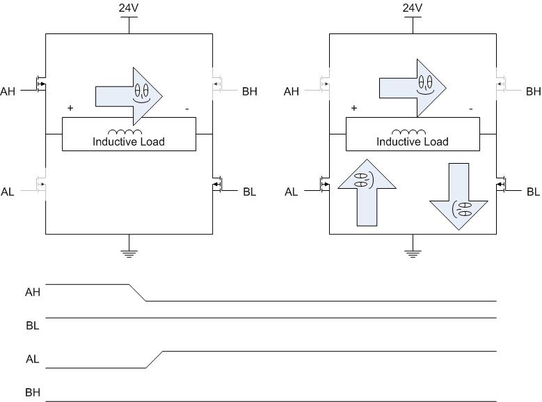
In Fast Decay Mode we use the opposing FETs to offer an alternate path for the current to flow through. Notice that it looks identical to the polarization in which we allowed for the current to flow in the opposing direction. However, it is very important we remember current does not tolerate abrupt changes. Hence, long before the current can flow in the opposite direction, it must decay to zero. Then, it can start flowing as we saw before.
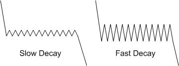
Fast Decay Mode is called as such because this is the fastest the current will die to zero. Notice you are basically placing a voltage source plus two voltage drops (there is a voltage drop across each FET given by the current multiplied by the FET RDSon) across the inductance. Since the inductance voltage can only be as large as the voltage source, the new voltage we are applying to the inductor is larger and as such will fight considerably hard for the already existing current to die out.
Below my two H Bridge drawings I am showing a possible way in which we can disable/enable the FETs. Remember Shoot Through is forbidden, so we must disable one FET before we enable the other one. It must be a break before make kind of deal. The speed at which the FETs are turned ON and OFF is in the nanoseconds range. Often, anywhere in the vecinity of 100 to 200 nano seconds. You may be asking, how about the current during these 200 nano seconds? Can it damage my already disabled FET? Luckily, FETs are intrinsically built with a body diode which will easily carry this current through this brief period of time. Anything longer than the 200 nano seconds, and all bets are off. You could of course design the body diodes to be large and powerful, but what’s the point? Shortly after we will be enabling a way better path which is the opposing FET!
A very important distinction to be made is between asynchronous and synchronouse current recirculation. If diodes are used (and there are reasons, such as improved thermal release, in which we will want to use external diodes instead of the FETs, a good example being the DRV8811), then the current recirculation is said to be asynchronous. This is because you are not controlling the occurrence of the alternate path creation. It will happen, but you do not control when this happens. If on the other hand, the H Bridge control logic has to take care of enabling and disabling FETs in order to promote an alternate path, then the current recirculation is synchronous. Just an important note, as both are still commonly used today!
Slow Decay Mode
In Slow Decay mode we use the FETs on the same H Bridge segment. Per example you can use either both high side FETs or both low side FETs. The typical convention is to use the low side FETs.
The idea behind this method is that current is allowed to decrease through zero as the inductor recirculates the current through a resistive path. Notice that as both low side FETs are enabled, the current is basically dissipating a voltage across the two FET’s RDSon. It is called slow decay because although current eventually decays to zero, it takes longer than fast decay mode. This makes sense as we are not applying a voltage opposing the current, which would definitely be the fastest we could fight the existing current.
How slow the decay mode is depends on the motor inductance and the FETs RDSon. The smaller the RDSon, the longer it will take for the current to decay to zero.
When it comes to DC motors, however, there is a very interesting effect while using this decay mode. While on fast decay mode the DC motor rotor coasts down in speed, with slow decay mode the rotor stops very quickly. This is because as can be seen by the above picture, you are shorting the DC motor terminals. This in essence implies the BACK EMF voltage source inside the motor to be shorted. And if there is no BACK EMF, there can be no speed. One is directly tied to the other. We call this phenomenon braking the DC motor or the collapse of the Back EMF. Braking is vital when you want to stop your motor very fast and possibly obtain a particular position. With coasting, this would not be possible, so be aware that selecting slow decay or fast decay with DC motors is not a trivial endeavor.
I like to point out, when I discuss slow and fast decay mode, that the names “slow” and “fast” are pertinent to current, not to DC motor speed. They imply a direct relationship with how fast the current decays through the winding. However, when it comes to how fast the DC motor speed decays, it is the total opposite. Kind of annoying, but I guess one thing leads to the other. So be careful not to think that fast decay will stop the motor very fast, because it is actually the opposite.
Mixed Decay Mode
There is one third of current decay which we call Mixed Decay Mode because it is actually a mixture of Slow and Fast Decay modes. By definition, you inccur in Mixed Decay if through the entire current decay cycle a percentage of it is slow and the remaining percentage is fast. Why do we need this feature? In DC motors it is pretty much unused, but when it comes to steppers, specially while microstepping, Mixed Decay is a must!
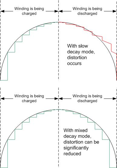
This may be a little bit advanced, but what happens is that as you are trying to synthesize a sine wave across your stepper motor winding, drawing said wave shape will become harder at some points in time. Per example, when you are charging the winding (angles of 0 to 90), it is very easy to superimpose the waveshape of a sine wave. But when you are discharging the winding (angles of 90 to 180), then the motor inductance will dictate whether you can discharge fast enough or not. If the motor inductance is too high, chances are you will not be able to superimpose the correct sine wave shape and deformation occurs. This is because the decay mode is too slow!
So a solution would be to use fast decay. This will definitely solve the problem, but another problem occurs. Fast decay mode has the side effect of high current ripple. Remember the current is swinging considerably more than on slow decay mode. This poses a few unwanted problems such as EMI magnitude increasing (larger current peaks are of course gives a stronger radiation) and more audible noise, depending on the current chopping frequency.

So what we need is an in between. Some decay rate that is not too fast or too slow. Mixed Decay mode gives us that. Some devices will allow you to control the exact rate of the mixed decay mode. The DRV8811 is a good example. Other devices, such as the DRV8824 and DRV8825, just give you a fixed rate of mixed decay mode. For most applications, this is enough.


48 comments for “Slow, Mixed and Fast Decay Modes. Why Do We Need To Complicate Things?”