If you have acquired or built one of my bipolar stepper motor drivers with up to 2.5A current capability and internal microstepping indexer, you could be asking, “How do I get this little guy started?” That is indeed a very nice question and although I tried to make the module as easy to use as possible, the levels of flexibility do add some minor complexity to it.

Figure 1
The quickest way to wire the board for operation with your own micro controller (MSP430, AVR, Arduino variety, 80C51, Basic Stamp, Propeller, PIC, etc) can be seen on FIGURE 1.
Header connector J3 accepts all the control signals you will need to deal with as well as low voltage power source, VDD. VDD is often 3.3V but it can go as high as 5V. From my microcontroller, I am driving DIR, ENABLE and STEP. I often ignore FAULT as I am assuming that everything is going to work. If there is a fault, however, this signal is available for your usage.
Notice I have directly connected to VDD, the SLEEPn, USM1 and USM0 signals as there is no need to control this with my microcontroller. However, if your application requires low power mode in order to preserve battery power, then I recommend you drive nSLEEP with your microcontroller.
Luckily, there is an easier way to set these three signals (nSLEEP, USM1 and USM0). I knew some people would use these drivers with their own PC CNC router (small form factor, of course) and all they would need are the DIRECTION, STEP and ENABLE signals. In this case, there are jumpers which can be placed so that the three signals question can be tied to VDD or GND depending on what you want to do.
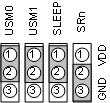
AE MDL STPR1 Typical Jumper Configuration
Figure 2 shows the typical jumper allocation I would expect to see on most setups. However, flexibility is there if you want something different. USMx will choose degrees of microstepping. A small table on the back of the board shows the different combinations. Unfortunately, I messed the silk screen so that both cells contain UM1. It should read UM1 and then UM0 (center cell is UM0). I will certainly fix this on my next revision.
SLEEP pretty much has to be jumpered to VDD. Jumpering SLEEP to GND renders the board useless as the device will be disabled. It just made the layout and assembly processes easier.
SRn has to be tied to GND if you do not have the external Schotky diodes. The back of the board contains the footprint where some MBRS360 could be soldered into. I do not sell the boards with these diodes as they are not 100% needed. If you want to run at very large currents, then the diodes are recommended as they take some of the heat away from the packaging. If external diodes are to be used, then jumper SRn to VDD.
Final Connections
Last two things to take care of are connecting the bipolar stepper motor to the J1 connector. This is no biggie, really. If your motor is a four wire connector, it is a matter of just plugging it in. Direction of rotation will be affected by which wires end up being A+/A- and B+/B-. Reversing the wire polarity should do.
In the same fashion, connecting power on J2 is equally easy. However, do note that connecting reversed power will instantly destroy the driver part, so make sure proper polarity is observed.
8 comments for “Connecting the AE-MDL-STPR1 Bipolar Stepper Motor Controller”