Most of my firmware applications will have a very simple real time operating system running in the background and calling one out of eight tasks every 250 us. What this means is that each task is called every 2 ms, or 500 times per second. I will not discuss the real time operating system on this post as it is quite simple, but if there is interest, I can detail on a later writing. I will however offer a high level diagram of how it all looks on figure 1.
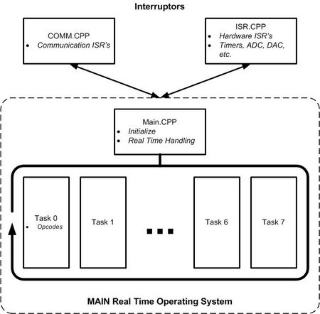
Notice the main function is in charge of initializing it all and then sequentially calling the TASKs. At this point in time all we need to know is that I have placed all of my opcode handling on the first of the tasks, in this case the one residing inside the code module TASK0.CPP. But before we go into this code, lets take a look at the upper side of the diagram where we see two files in charge of interrupting the normal flow. It is crucial we understand why they are here.
One of them has the interrupting sources for the communication blocks and the other every other piece of hardware that can interrupt the CPU, such as timers, ADC’s, DAC’s, GPIO’s, etc. I like to keep them separate because the serial stuff I will reuse unchanged from application to application. Everything else, however, is strictly pertinent to the application. For example, a timer will be used as a PWM generator when driving a brushed DC motor, a square wave generator when driving a stepper, or a DAC updater when driving a microstepping engine. This is the code that changes, whereas the COMM.CPP code remains unchanged. In fact, if I wanted to make the buffers larger or smaller, I would go to the COMM.H header file and change a couple of defines I have allocated for that purpose.
Coming back to the communications module, COMM.CPP, in here we will be receiving and sending bytes. So why not poll for bytes? Yes, you could do this, but if there is an interrupt, why not? It is automatic!
The microcontroller UART has an Interrupt Service Routine (ISR) in charge of receiving data bytes, so we will take advantage of this. In this case, I have coded the respective ISR into updating the serial reception buffer called SerialBuffer, whenever a byte is received. The code is attached below:
#pragma vector=USCIAB0RX_VECTOR
__interrupt void USCIAB0_Receive(void)
{
SerialBuffer[SerialPointer] = UCA0RXBUF;
SerialPointer += 1;
if (SerialPointer == SERIAL_BUFFER_LENGTH)
{
SerialPointer = 0;
MessageComplete = true;
}
}
Look how simple it is to receive the five bytes with the microcontroller taking care of all the heuristics around this task. Before you would have needed to code the serial port in code which is a nightmare in itself as you need to be continuously polling GPIO inputs. Instead, with nowadays microcontrollers you just wait until a data byte makes it through the hardware port and then read the data from the internal buffer (UCA0RXBUF) and into your own buffer (SerialBuffer[]).
As I explained on the introduction, I like my buffer to be a 5 byte array. It can be as long as you want, but the length is important as every time a byte is accepted, a counter called SerialPointer is increased. When the SerialPointer is equal to the number of bytes we want to receive (SERIAL_BUFFER_LENGTH ) we set a flag called MesageComplete. We will soon see TASK0 is waiting to see when this happens. The last thing our reception ISR does is clear the serial communications engine so that it is ready for a new packet.
As TASK0 executes, the first thing it does is check whether the MessageComplete flag is set or not. If it is not set, the MCU exits TASK0 and the MCU enters sleep mode until it is time to execute a new TASK (or TASK1, which always follows as TASKS are executed in sequential order). When the flag is set, however, it then enters the function that decodes the opcode and executes the command. This function is nothing other than a SWITCH CASE statement where the OPCODE byte (SerialBuffer[0]) is used as the switch element.
I have copied the basic portion of TASK0 code that I start with more often. The idea is to add our own commands to the structure below:
void Task0(void)
{
if (MessageComplete)
{
SerialOutBuffer[0] = FIRMWARE_REVISION;
SerialOutBuffer[1] = 0;
SerialOutBuffer[2] = 0;
switch(OPCODE)
{
case (READ_MEM):
int * MyPointer;
int Address;
Address = (SerialBuffer[1]*256 + SerialBuffer[2]);
MyPointer = (int *) Address;
SerialOutBuffer[1] = (*MyPointer & 0xFF00) >> 8;
SerialOutBuffer[2] = (*MyPointer & 0xFF);
break;
case (WRITE_WMEM):
int Data;
Address = (SerialBuffer[1]*256 + SerialBuffer[2]);
Data = (SerialBuffer[3]*256 + SerialBuffer[4]);
MyPointer = (int *) Address;
*MyPointer = Data;
break;
case (WRITE_BMEM):
char BData;
char * MyPtr;
Address = (SerialBuffer[1]*256 + SerialBuffer[2]);
BData = SerialBuffer[3];
MyPtr = (char *) Address;
*MyPtr = BData;
break;
case (RESET_MCU):
WDTCTL = 0x00;
break;
}
MessageComplete = false;
SerialOutPointer = 0;
UCA0TXBUF = SerialOutBuffer[SerialOutPointer];
IE2 |= UCA0TXIE;
}
}
The first thing we will do is fill up the SerialOutBuffer with dummy bytes. But what is this SerialOutBuffer[] array?
If SerialBuffer is the array where we store the five bytes that go into the serial port, the SerialOutBuffer is the three byte array that the microcontroller will send back to the computer as an acknowledgement. These dummy characters can be updated with your own on those opcodes in which it makes sense to do so. For example you can see on the READ_MEM opcode we update the SerialOutBuffer bytes 1 and 2 with the contents of the memory address we want to read from.
After initializing the output buffer, we can not decode the input buffer’s opcode. Since it is always byte #0, this is what we look at with our SWITCH statement. Once inside the Switch structure, we can now write a different CASE statement for every possible command you want to execute. It is that simple! You can see on the example above a series of very useful commands such as the ability to write a byte or a word, or read a word back from the microcontroller.
We are done! It is not time to clear the MessageComplete flag. After all, we do not want to execute the same command over and over, every 2 ms! We will also initialize the serial port to send out the three byte array. For this purpose we use a different interrupt subroutine, which also resides on the COMM.CPP module.
#pragma vector=USCIAB0TX_VECTOR
__interrupt void USCIAB0_Transmit(void)
{
SerialOutPointer += 1;
UCA0TXBUF = SerialOutBuffer[SerialOutPointer];
if (SerialOutPointer == SERIAL_OUT_LENGTH – 1)
{
IE2 &= ~UCA0TXIE;
}
}
Notice it is pretty much the same concept, except that in this case we get the data bytes from our array (SerialOutBuffer) and we put them into the internal output buffer (UCA0TXBUF). The ISR will be called every time a byte is successfully sent, at which time we increase the SerialOutPointer counter. Once we have submitted all the byes out, we disable the serial communications port. TASK0 will enable it again once it is time to communicate the next time a command has been successfully decoded and executed.
And that’s it! Everything else is your own code which of course I can not help you too much with as then it would be my code ;-). Do note that you have a powerful tool at your disposal. Once we pair this with a packetizing application, you will be able to accomplish great things!