When I decided to build the Avayanium 3D Printer, I scoured the web while trying to find the perfect topology to attack. There are so many of them out there, I was kind of overwhelmed. Luckily, one day I saw a picture for a gorgeous looking 3D printer known as Maker Gear’s M Series printer and my search was over. I am under the impresion there must be other units following the M Series printer topology, with a single stepper per axis and a single threaded rod for the Z Axis linear actuator, but I guess that is irrelevant. What truly matters is what are the implications of following this topology. As we will soon see, there are both advantages as well as disadvantages for an implementation of this sort.
I will not detail on this blog post how the X, Y axes and the extruder actuator work as there will be other blog posts relating to those. What I want to discuss, however, is the Z Axis. I believe this is where the great majority of differences arise, when comparing to other printer topologies. For example, in my implementation I am using a single threaded rod to actuate the Z Axis, when what you see the most out there is either two or even four threaded rods to articulate the vertical motion which will lead to proper de-slicing as the 3D printer part is printed.
At the same time, my implementation only uses one stepper motor when a good deal of dual threaded rod implementations will utilize two steppers. On the quad threaded rod, I do not believe four steppers are used, although I have seen plenty of timing belt pulleys and longer belts increasing the BOM’s price tag.
As a result, we can conclude my single threaded rod implementation is advantageous because I am saving funds on materials such as stepper motors, motor drivers, threaded rods, timing belt pulleys and belts. Well, I’ll be darned, that sounds like a no brainer!!!! But if it is so good, why don’t we see a great majority of implementations out there going this route?
Well, we all know lunching for free is not that much feasible. And to make matters worse, tradeoffs are always creeping up at us, which always translates into getting something improved at the expense of messing up something else. No difference here! We may have saved a lot of dough on materials and made our implementation far much simpler, but we have also made it much more unstable.
A single threaded rod with a single stepper means we have lots of mechanical support on one side, with a complete lack of it at the opposing side. Why this is a problem should not require much of an explanation, but just in case let me tell you what happens. The table, which is the area where your print will form, has to remain a planar surface at all times and under all conditions. When the extruder is applying plastic, it assumes the XY plane remains true.
Unfortunately, when the table is stronger on one side than the other, what will happen is that its surface will flex. In other words, the XY plane will no longer be a single plane, but a collection of them. Ehhh… BAD!!! This may not happen during the first stages of a print as there is not a lot of weight, but the more plastic you deposit, the worse it gets. Those XY coordinates close to the thread and the axis, where the table is sturdy, will maintain their Z coordinate, whereas those XY coordinates far away from the thread, where most of the flexing is taking place, will be at a different Z coordinate than supposed. Figure 1 attempts to illustrate what I mean:
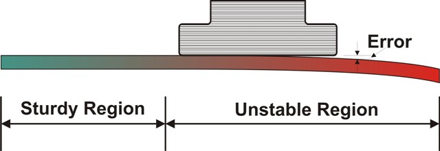
Clearly using two threaded rods solves this problem as it eliminates the table flexing. Of course now you need to not only use multiple stepper motors and an equal amount of stepper drivers (you should not connect two stepper motors to a single stepper driver module even if it appears to work), you also need to make certain they are identically linked in the Z axis. If for any reason, one stepper is out of sync with the other, then the table will be at an angle, which is an even worse problem than the first we were trying to solve. Granted that if the steppers are perfectly linked and their respective rods are perfectly graduated, then there is nothing to worry about.
I wanted to steer away from the mega mess that is to ensure both steppers and their threads are perfectly graduated. Makergear’s M Series printer solves the problem by using a super sturdy table system. I could have done the same but I found a different solution which gives the same results.
By retrofititng a Tol-O-Matic pneumatic actuator’s metal assembly I was able to generate a very sturdy Z Axis. On the following video I detail how I transformed a pneumatic actuator into a threaded rod based linear actuator. In a subsequent video I will detail how to add the improved stability which will allow for a long table to remain sturdy across the XY plane. Hope you find this short report very informative!