A First Look At My 3D Printer Extruder
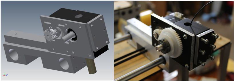
It took me about 48 hours to get this puppy complete. From conception to implementation! I must admit, however, that I have had the idea of how it should look and work lingering in the back of my mind for a few months, but this past Tuesday I dedicated about 10 straight hours to draw the model in Autodesk Inventor and then on Wednesday at 6:00 AM got up early to start the creation process. 24 hours later, I had a prototype assembled and I was ready to shut my eyes for a little bit. It was a long night…
OK, I guess that is not 48 hours, but more like 34, but who is counting?
Anyway, when it comes to designing an extruder, what are the challenges? First of you want the thing to grab that thread and push into the hot end nozzle with the right amount of force. Any slippage means you will end up not supplying as much plastic as the 3D printer software thinks it is deploying. Bad news! What this means is we must find a way to apply pressure from the thread delivery shaft, as well as the opposing ball bearing. What I have seen people doing is use springs and a back plate to force the opposing ball bearing into the thread.
What all of this means is we need a piece with a hollow cavity to take all of these components (ball bearings, shafts, nozzle cylinder, etc). If you have a 3D printer, to build a piece like this is beyond easy! How the hell do you make this without a 3D printer then? How about a CNC Milling machine or router? Good luck with that, because you can’t!
Before I am called an idiot who doesn’t know what he’s talking about (which most likely is the case) allow me to add another requirement: in one piece. Try to use a CNC milling machine to build this part in a single piece, and if you can do it, please lets make an appointment so we can meet and I bow to your awesomeness.
The solution? Let’s not do it in a single piece! Easy, right? Ehh WRONG! If you are like me, then you must be one of those individuals for whom any assembly with more than one part are able to do everything except align together. So as I contemplate my options I am almost convinced this is not going to work.
Shame on me!
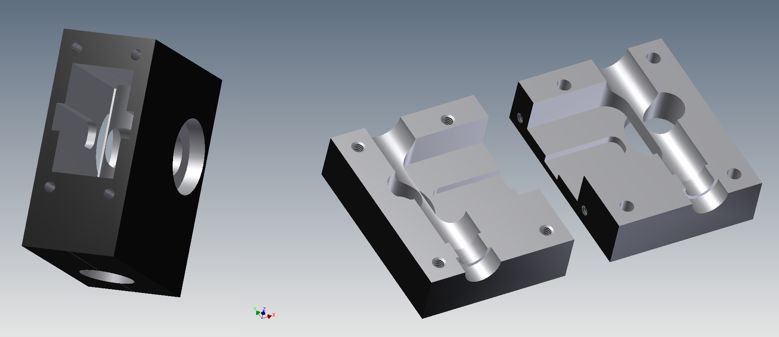
As I draw this part:
I am convinced there is no way I can build this on my PCNC1100 milling machine. Yes, the machine is awesome and even when I am not a machinist, I have been able to make lots of parts with so much accuracy my jaw requires reconstruction after I get them out of the table. But this part? Come on! It is too complex! To my amazement, apparently it isn’t. Here is a picture of the two parts after I had removed them from the last milling operation.
Now, do not think this was a single step operation. The first two halves were cut with G Code program with 7 tool changes, out of a single piece of plastic. I then needed to move each piece around four more times to cut the ball bearing side, the cylinder cavity and the back side mounting screws. The two halves aligned so well, I couldn’t believe it. As Yoda would say: “Always with you it can not be done. Hear you nothing that I say? You must unlearn what you have learned!”
In theory, I should have been able to cut every detail in a single job. There are CNC operations such as waterline roughing and waterline finishing, which if tuned properly, and if the right tool is used, should just cut this geometry in basically two generated tool paths. That would most likely require a seasoned CAM artist. I tried for a few hours and eventually gave up as it was clear the CAM program was going to do everything except what I needed it to do. I chose the “slower” method (me moving the pieces around the vise and running multiple jobs with multiple operations), which at the end resulted in much quicker turnaround as I ended up with the part I needed.
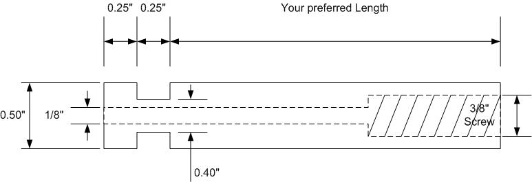
Once I had the two plastic parts tapped and ready to go, I was able to focus on the peek cylinder. This is actually a fairly simple piece to manufacture if you have one of those small lathes. I got mine on Harbor Freight when they had the 20% coupon and it was on special at $400, so I think I paid something like $350 after tax. What an invaluable tool this has been! No science on how to make this, it is just a peek cylinder which you will drill through with a small diameter drill to allow for the filament passage. On one side you will then drill so that you can tap with the screw you want to use for your nozzle and hot end. In my case I used a 3/8″ 16 TPI screw. Notice this is the US, so everything is in English, but to be honest, these measurements are not Alien technology. As fas as I know, you can make them whatever you want. Of course don’t make the cylinder one mile long as that peek rod will be too expensive. Well, actually the real reason is the longer you make it, the more it can deflect during run time. Here is a diagram of some of the measurements I did need to follow in order to properly match the cylinder to the housing.
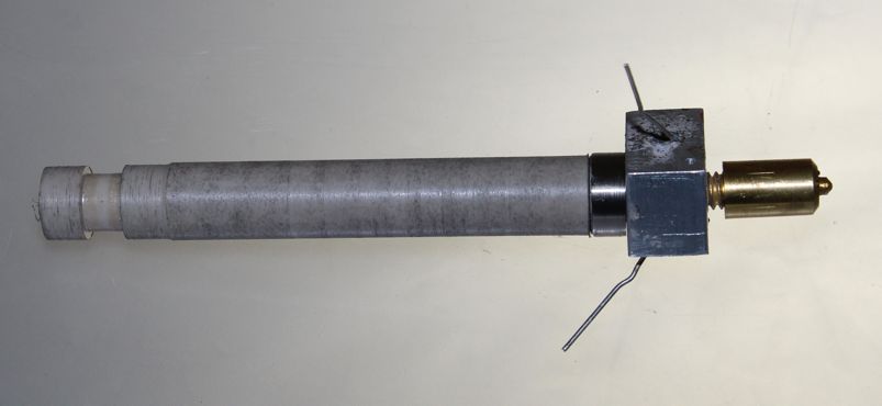
Here is a picture of my cylinder with the hot end mounted.
A few notes on my hot end. Nothing new here. I got this from the reprap wiki page. I am using an stainless steel screw to interface the brass threaded rod into the peek. Why? I searched for a table with thermal conductivity and it became apparent Stainless Steel (16 W/m.K) is not as conductive as brass (109 W/m.K). Aluminum is 205 W/(m.K) and Peek is 0.25 W/m.K. So what’s my reasoning here? We want the aluminum and the brass to get very hot, that’s for sure, as that is how we will melt the plastic. The rest of the system, however, we want to remain cool. We don’t want to melt the printer! This is why Peek is used. It is the insulator. However, I saw Makerbot using a stainless steel screw to work as an “insulator” and that apparently worked good enough so I thought of doing both. Let me add I am no mechanical engineer and I was never into my Thermodynamics introductory course so there is a good chance my reasoning here is quite flawed and preposterous. I am certain those who know will have no problem in pointing it out when the time comes…
Here is a picture of my current cylinder:
I will be redoing the tip as I know for a fact the hole is big enough to print cruise anchor ropes. I am using the power resistor method and I will use a DRV8844 to drive it.
The last portion of my extruder is the pushing bearing which is just a bearing mounted on an 8 mm shaft which will roll through the aligning canal on the body’s back compartment. In order to apply pressure, the back plate will be mounted with four screws bolted into the body but with springs into the back plate. This will make the back plate push into the body. Two screws are used to apply the same force into the shaft. These shafts were machined manually and here is where most of the slop can be found. Luckily, it is not enough to render the creation completely useless. I can feel a little bit of unwanted friction, but I think the stepper will be able to overcome it.
Download The Inventor Files Archive:
Feel free to download this archive (AvayaniumExtruderShare) containing the files I used to create the Avayanium Extruder. You should use these files for reference and maybe to get started on your own. I cannot guarantee these files will give you the ultimate extruder in the face of this planet or that you will be able to get rich overnight with them. If you do manage to use them to get rich, feel free to send me a souvenir with your creation.


